Notes of 3D Gaussian Splatting.
The commonly used representations of 3D content can be categorized into two categories:
- Explicit representation, for example:
- Mesh
- Point Cloud
- Implicit representation, for example:
- Surface Function
- NeRF
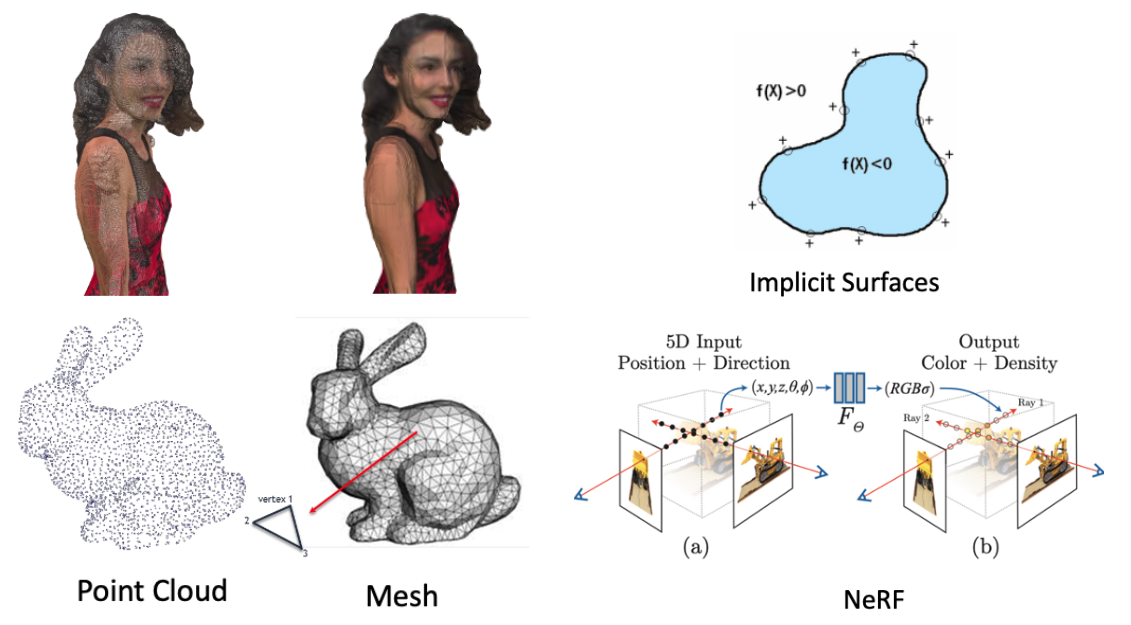
For explicit representation, Point Cloud is the most popular 3D representation in the research area. While NeRF is the most popular one in implicit representation.
Point Cloud is a set of points, each point consists of position (X, Y, Z) and texture (R, G, B). The point cloud is a natural representation, as our world consists of particles, like electrons, neutrons, etc. The disconnected and unstructured nature makes them scalable for rich processes and parallelizable for rendering.
The problem of the point cloud, or point-based representation, is that point sample rendering suffers from holes, causes aliasing, and is strictly discontinuous. To address this problem, some works propose to extend the point-based representation to other shapes like circular or elliptic discs, ellipsoids, or surfels. This kind of extension is called “splatting” and the point primitive is called “splat”, which is very vivid.
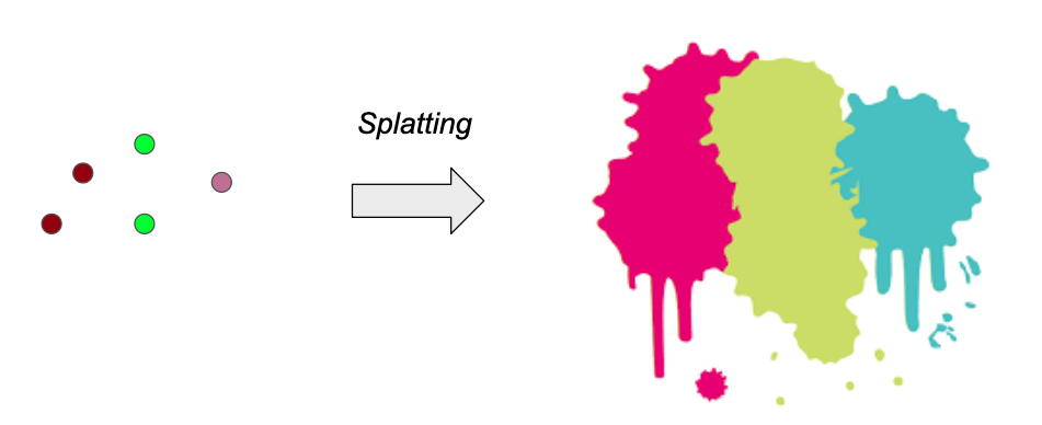
Among those splatting works, there is a work [1] that proposed elliptical Gaussian as a representation and developed a series of techniques to render the splats. This work is the backbone of a recently very hot technique, named “3D Gaussian Splatting (3DGS)” [2]. We can see that 3D Gaussian is a very “ancient” concept and the researchers have already explored it for a decade.
First, let’s introduce 3D Gaussian itself.
A 3D Gaussian is parametrized by:
- Mean $\mu$ interpretable as location (x, y, z);
- Covariance $\Sigma$;
- Opacity $\alpha$ ;
- Color parameters, which can be (R, G, B) or spherical harmonics (SH) coefficients.
Two parameters may confuse the readers: Covariance $\Sigma$ and SH.
- The Covariance $\Sigma$ defines how the 3DG is stretched or scaled. It can be simply regarded as a parameter that enables a 3D point to be described as an ellipsoid in the 3D space.
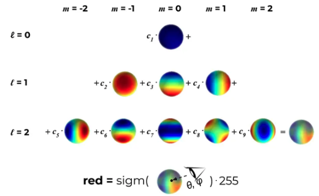
- SH are special functions defined on the surface of a sphere. One can regard it as basis functions that define a color representation. The rendered color is defined by the weights of the basis functions. For every 3D Gaussian, we want to learn the correct coefficients so that when we look at this 3D point from a certain direction it will convey a color the closest to the ground truth one.
- It is a way to represent view-dependent color. We can safely use RGB, which won’t affect the visual quality a lot actually (according to simple experiments).
The main contribution of 3DGS is the optimization part: how to train and optimize the 3DG, and how to render them in real-time.
Specifically, the contributions of 3DGS are the following (as listed in the paper):
- Use 3D Gaussians to represent the 3D scene.
- Several tricks to create and optimize the 3D Gaussians for accurate representation
- Optimization using gradient descent
- Adaptive density control to increase or decrease the number of 3DG.
- Use GPU for real-time rendering.
Next, I will introduce 3DGS in detail following the training pipeline.

Initialization. The initialization of the 3DG set is based on a point cloud produced by Structure-from-Motion (SfM). In detail, the covariances of 3DG are initialized to be isotropic as spheres. The radiuses are set based on mean distances to neighboring points such that the 3D world is nicely covered and has no “holes”.
The logic behind this operation is quite simple: for 3D construction, you always have to know the camera matrices which are usually obtained by SfM techniques. Therefore, the side product of SfM, i.e., a sparse point cloud, is naturally a good initialization. Starting from SfM is not a must, as the ablation study part in this paper suggests, a random initialization can be used with the risk of a potential loss of the rendering quality.
Training/Optimization. After initialization, the second step is to optimize the 3DG to approximate the real 3D scene. Stochastic Gradient Descent (SGD) is used for optimization. The loss function is also very simple and intuitive: L1 and D-SSIM (structural dissimilarity index measure) between the ground truth views and the rendered views from 3DG. The training step can be sped up by GPU.
Adaptive Density Control. This can be regarded as an additional optimization step, to adjust the number of 3DG, thus enriching the details of representation, or reducing unnecessary costs caused by too many 3DG.
The authors define two cases where increasing the number of 3DG is needed: (i) Under-reconstruction and (ii) Over-reconstruction. In both cases, the 3DG tends to have large view-space positional gradients, which is thus regarded as a criterion for the detection of both cases.
For the case of under-reconstruction, a copy of the same size is created and moved in the direction of the positional gradient. For the case of over-reconstruction, where a small-scale geometry is represented by a large splat, we split the 3DG in two, divide their scale by a preset factor, and initialize their position by using the original 3D Gaussian as a PDF for sampling. The process is shown below.
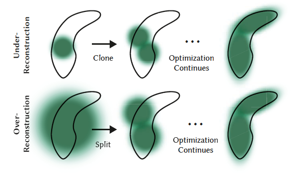
The authors use opacity $\alpha$ to identify the necessity of removing the 3DG. That is, removing 3DG that have converged to very low values of $\alpha$.
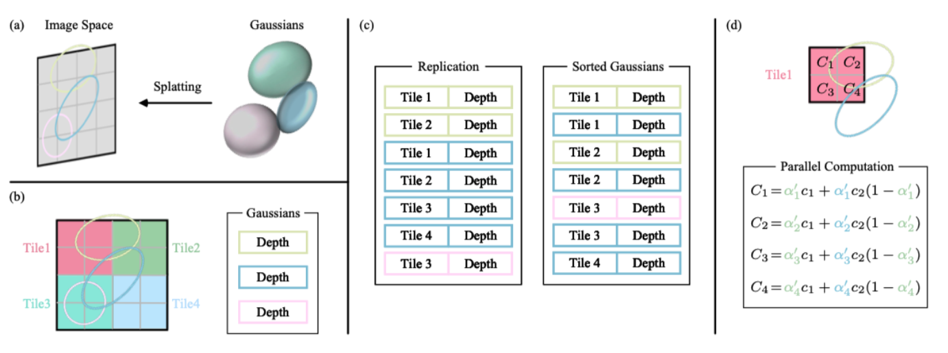
Fast rendering with GPU. To avoid the costly computation of deriving Gaussians for every individual pixel, the 3D GS technique shifts the focus of precision from the pixel level to a patch-level detail. Specifically, the 3D GS method starts by dividing the image into multiple non-overlapping patches, referred to as “tiles” in the original paper. According to the authors’ suggestion, each tile consists of 16×16 pixels. The 3D GS approach then determines which tiles intersect with the projected Gaussians. Since a projected Gaussian may cover multiple tiles, a logical approach involves duplicating the Gaussian and assigning each copy a unique identifier (referred to as a tile ID) corresponding to the relevant tile. After replication, the 3D GS technique combines the respective tile ID with the depth value obtained from the view transformation for each Gaussian. This process yields an unsorted list of bytes, where the upper bits represent the tile ID and the lower bits indicate the depth. By employing this strategy, the sorted list can be directly utilized for rendering purposes, such as alpha compositing. The figure below shows this process, which is captured from [3].
[1] Zwicker, Matthias, et al. “Surface splatting.” Proceedings of the 28th annual conference on Computer graphics and interactive techniques. 2001.
[2] Kerbl, Bernhard, et al. “3D Gaussian Splatting for Real-Time Radiance Field Rendering.” ACM Transactions on Graphics42.4 (2023).
[3] Chen, Guikun, and Wenguan Wang. “A Survey on 3D Gaussian Splatting.” arXiv preprint arXiv:2401.03890 (2024).
- 本文作者: YA
- 本文链接: https://shiyuang-scu.github.io/2024/03/19/Notes-of-3D-Gaussian-Splatting/
- 版权声明: 本博客所有文章除特别声明外,均采用 MIT 许可协议。转载请注明出处!


